


")

 (6)")
 (5)")
 (3)")
 (2)")
 (1)")


")
")
")
")
")
")


")
")
")


")
")
")
")
")
")
")


")
")


BUILDING MODEL AIRPLANES FROM BALSA WOOD AND TISSUE AND AIRPLANE DOPE AND MAKING THEM FLY…OR TRYING TO…IS A LEGITIMATE AMERICAN CULTURAL ICON.
Bob Benjamin's Master's Workshop Is Where Balsa Builders Belong
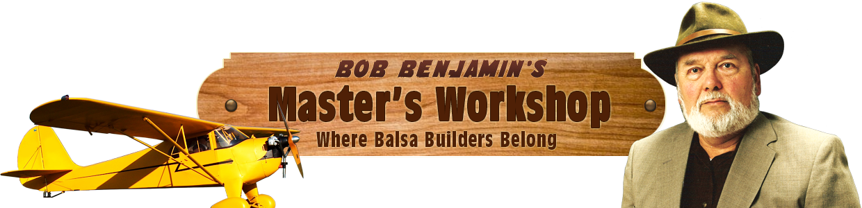
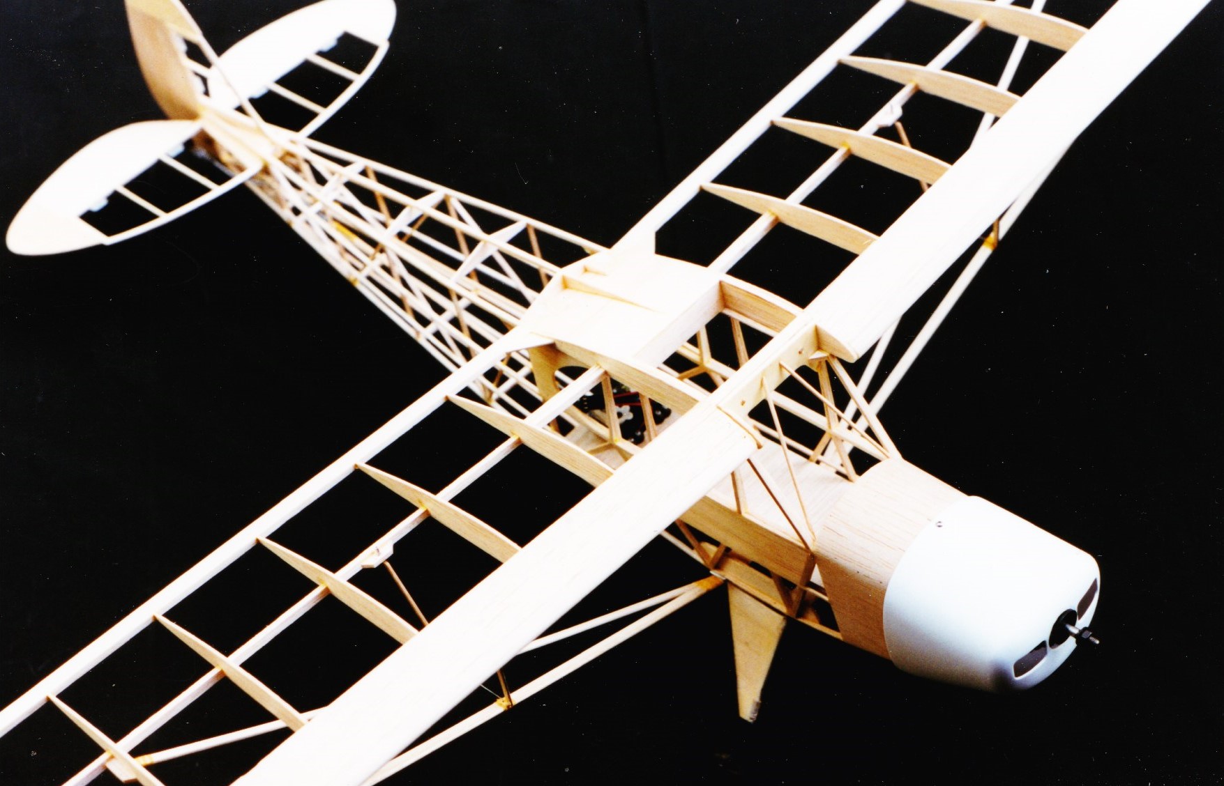
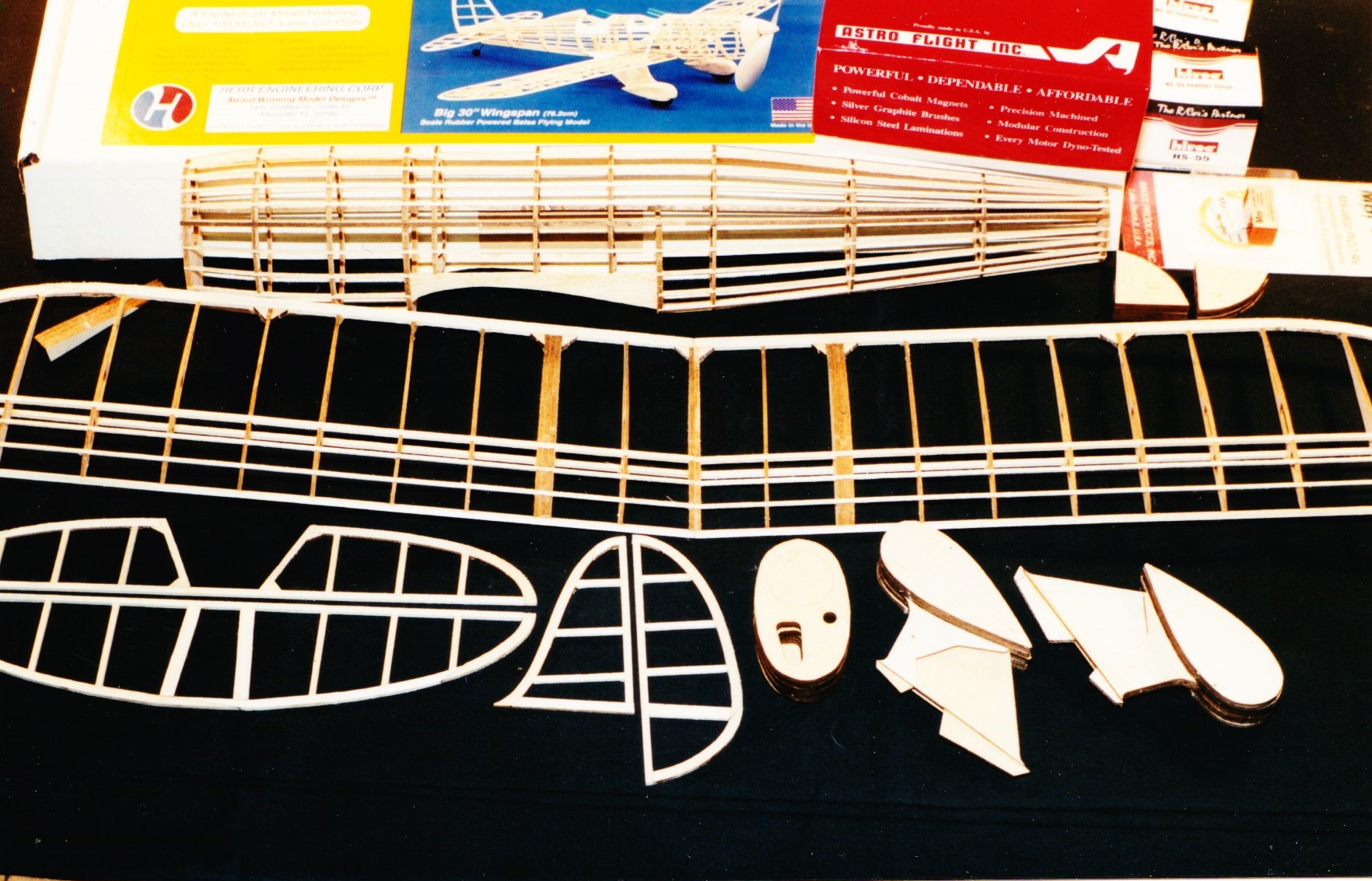
Back in those good old days all of us built our model airplanes the old way using balsa wood and fabric and dope and parts that you cut out yourself. When I was a little kid, you learned those skills or you did not get to fly. That’s what this Old Time Model Airplane Workshop is all about… sharing what I have learned over all those years about building model airplanes.
With experience and determination you could get wonderful flight performance out of the old models, but our technology of flight control didn’t even come close to matching the devotion we put into making them. No matter how good you became at building, no matter how well you learned to dope and sand and balance and trim and test and tweak, every effort you made at flying was by definition a gamble.
Since the late 1960’s it has become increasingly easy to buy miniaturized electronic treasures in the form of model radio control systems that bring you ever closer to being in the model to pilot it. The radios keep getting better… smaller and lighter and more powerful and more complex and less expensive…the stuff of dreams for real. Close alongside that progress, model airplanes have become bigger and faster and more impressive, and quicker and easier to build thanks to new materials and production techniques and mass marketing. This is fine if what you want to do is fly, but it doesn’t take long to realize that when the skill and devoted talent…the art of model building…get set aside, the soul of aeromodelling can get lost, too.
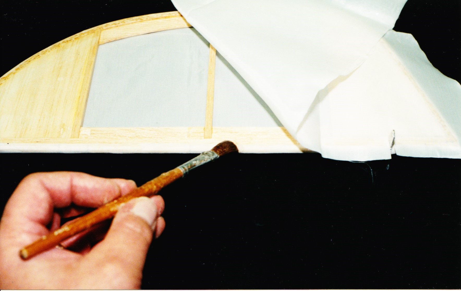
It doesn’t have to be that way. I have chosen to work at combining the best of today’s technology with the best of those old-time model building skills by building the very best electric powered RC scale airplanes I can. In my opinion that’s a direct route to my very own Golden Age of Aeromodelling. I’m inviting you right now to visit my shop whenever you like through this blog to see what I’m working on.
~Bob
