Now we need a cowl to finish off the front of what is turning out to be a neat model airplane. These days you can pretty well assume that something’s wrong if you don’t find a well made, shaped cowl of fiberglass, or at least vacuum formed ABS or styrene waiting for you in the kit box. You know what’s coming, next, right? Back when, that didn’t happen. If you wanted a cowl you had to make it, and the way the FlyLine Great Lakes was designed is pretty typical of what you could have expected to find. If you’re still with me now you already agree that these are really valuable model building skills to have, so…let’s make a cowl.
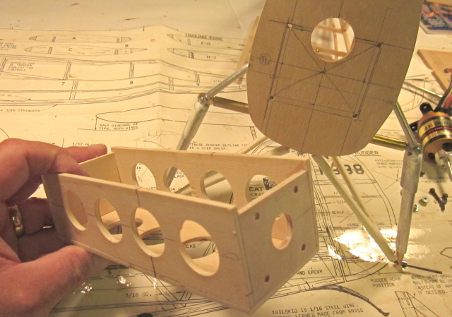
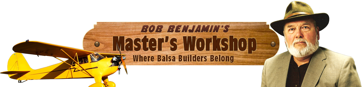
When I began building the fuselage I wasn’t sure exactly how I would end up doing the motor mount, so I cut a small opening to permit wiring and cooling air to pass through in the event everything else ended up screwed to the face of the former. It turned out that the best way to do the job ended up having the box assembly extend right through the firewall, so after I made the pencil layout that determined some of the mounting box dimensions, I used the same lines to define this cutout.”]
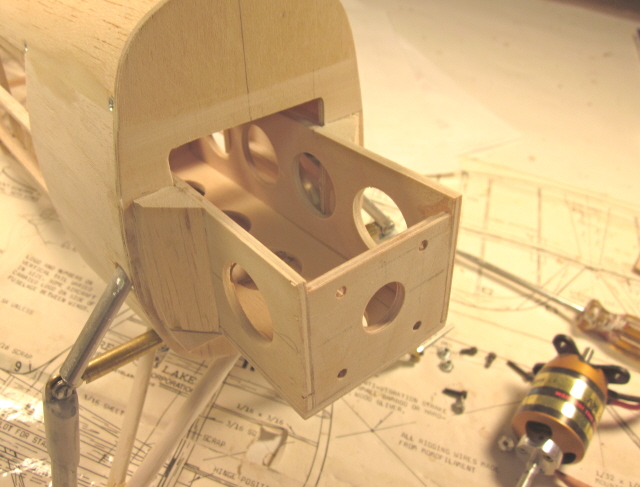
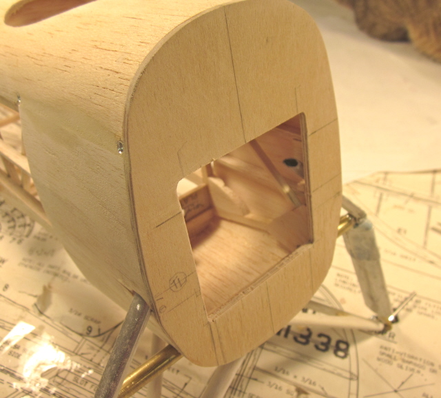
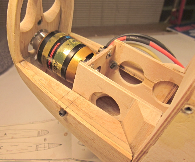
Here’s the finished mounting box securely glued in place through the opening in the firewall, with a couple of triangular section balsa corner blocks for reinforcement. I used a square to triple-check the alignment of the box with the firewall face during assembly.
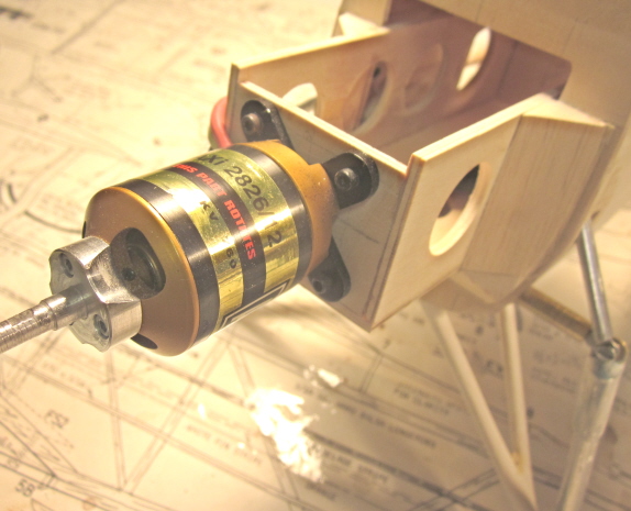
The AXI 2826-12 motor is exactly what this airplane is going to need. I get all my AXI goodies from Hobby Lobby. Rather than repeat all the tech specs, I’ll suggest that you go directly to their website for the good stuff … http://www.hobby-lobby.com/brushless_axi2826.htm. I used 4-40 socket head screws with blind nuts on the back side of the mounting plate to hold the motor in place.
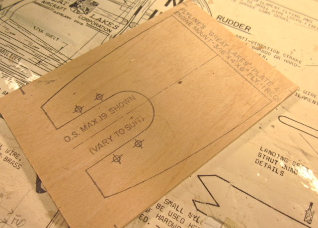
This is the original motor mounting plate, which I described earlier, as it comes out of the kit box.
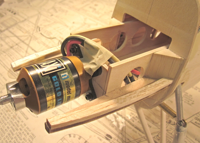
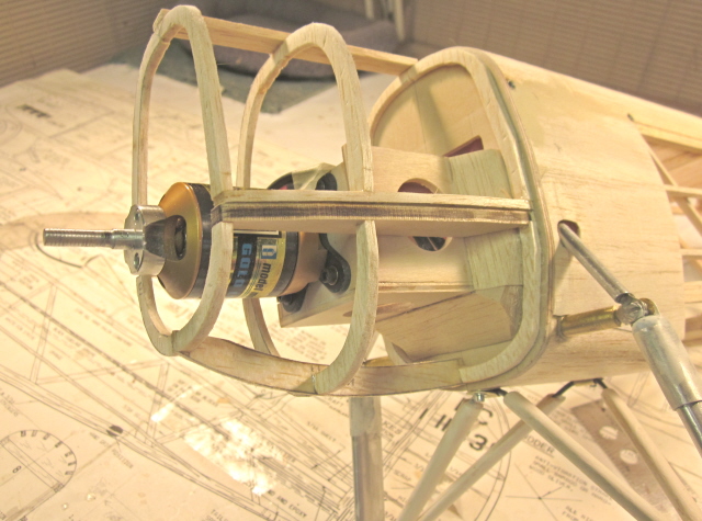
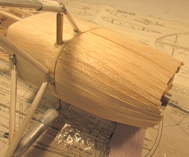
You’ll have to take a careful look at this one. I wanted to use to outline of the plywood mount to define the shape of the cowl just as it would have done with the original design, but the entire “middle” or inside portion of the part has become superfluous. Doing a little measuring, I determined where to cut two outer edges from the mount and spot-glued them to the mounting box and corner blocks along the thrust line (which is also becomes the parting line for the upper and lower cowl sections) . The 1/8″ balsa doublers you see above and below the plywood are the various “S” formers supplied in the kit as cowl parts.
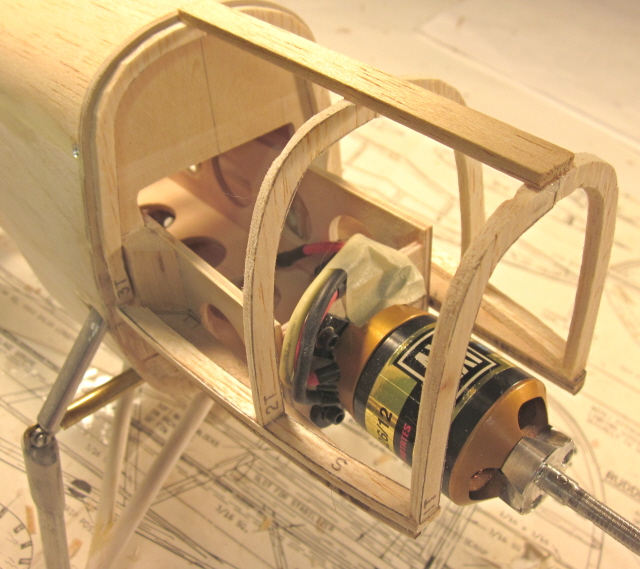
From this point on the cowl assembly proceeds pretty much as it’s shown on the plan. The cowl formers T-1 through T-3 are cut out in halves from the parts sheet and assembled in place on the horizontal “S” base plates. I have added a single strip of the 1/8″ x 3/8″ balsa cowl planking material to the top center to hold the formers in alignment while I handle the model.
The cowl bottom formers get the same treatment.
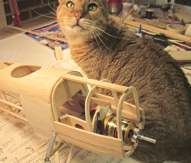
Sometimes I have help whether I need it or not. Atia did not want to get out of the picture. As for the cowl, I have started adding strips of the 1/8″ x 3/8″ balsa planking strips beginning above and below the parting line, working alternately left-right and up-down to maintain an even load on the former assembly.
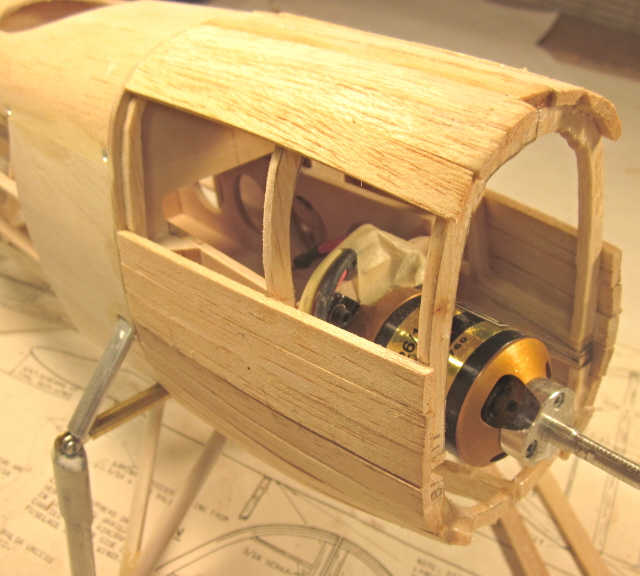
I am using a combination of medium/slow cyanoacrylate to attach each of the planking strips in turn.This gives me time to be sure each is in exactly the position I want, then hold it in place for ten or fifteen seconds for a good bond. Using older style adhesives here would demand pins, tape or some other form of clamping that would probably dig up and distort the planking strips. By looking carefully at the assembly I have competed, you can see that it helps to sand a bevel onto each of the joining edges to get a tight fit where the strips join. The better you make this fit, the less filler you will have to use later.
When the last plank is in place there should be no gaps or holes. A careful inspection will show you where I have tapered various strips so that all of them will fit properly as the cowl tapers toward the front.
Here’s the same deal from the bottom. There’s no magis to getting a planking job to fit this way…you just have to taper and bevel and trim each piece as you go along and MAKE IT FIT.
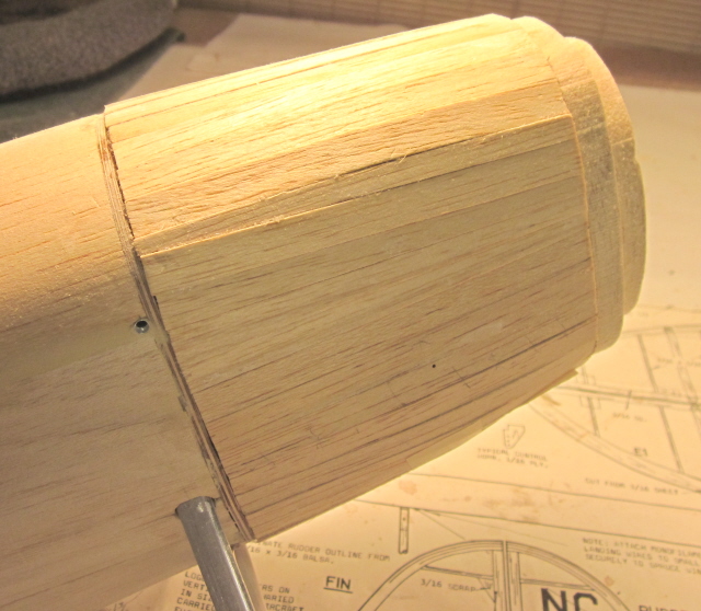
Here’s the same deal from above. Again, you can see where individual planking strips have been tapered to fit neatly as the diameter of the cowl decreases. I have added two pre-laminated face blocks to the front of the cowl.
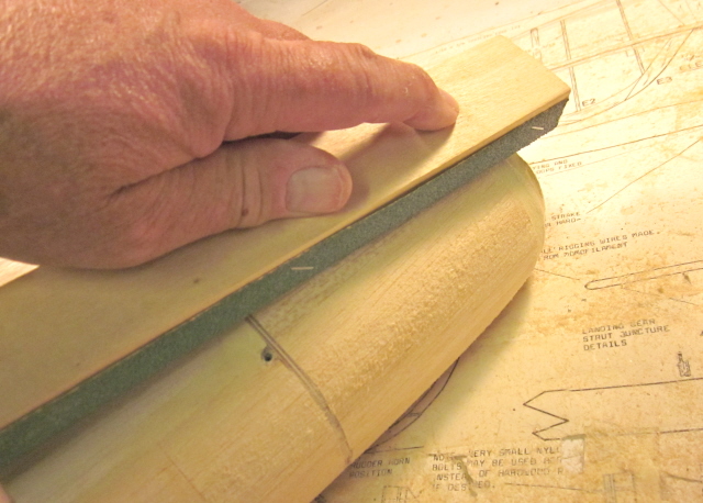
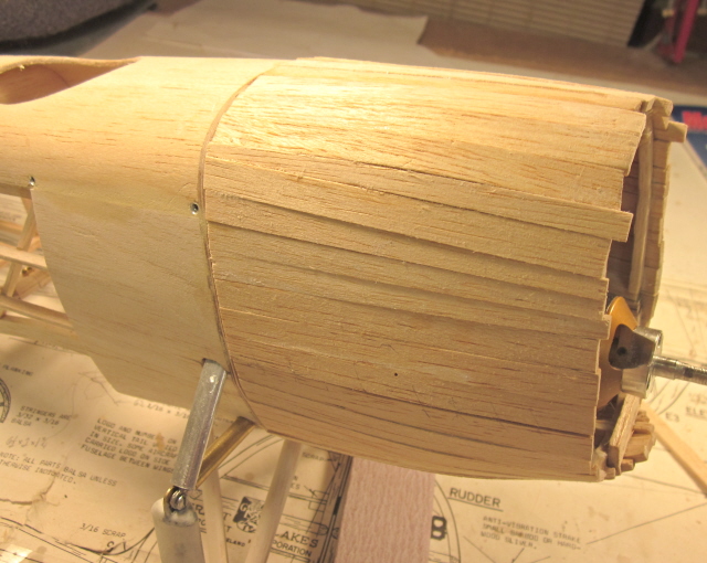
At this stage there is no substitute for the ol’ sanding block. Here I am still doing rough shaping using 40-grit autobody paper to cut through the various soft-to-hard transitions in the glued balsa structure without leaving bumps or ridges.
The entire cowl has been sanded to finished shape and smoothed with 100 grit paper, still on a block. There were a few spots where the 1/2″ balsa shhet cowl front laminations weren’t marked to be cut quite wide enough. I filled the little voids that resulted using Model Magic light weight spackle and sanded the resulting fills smooth.
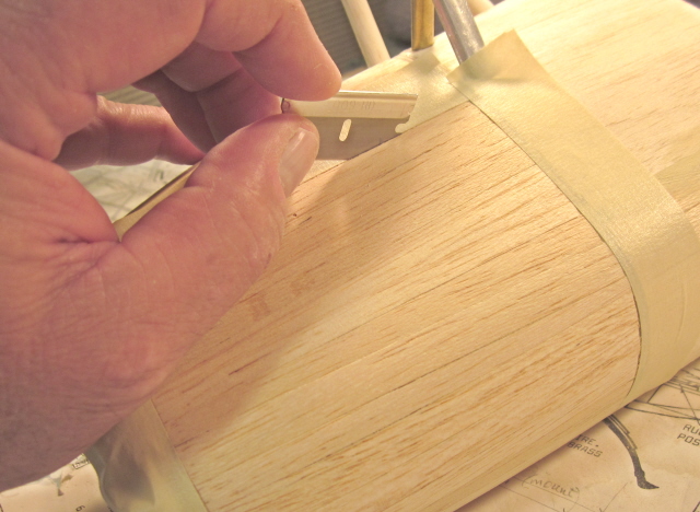
Now we have to start working on the inside of the cowl. Remember that I did a “spot glue” job on the plywood formers? I also left the rear (firewall) ends of each pplanking strip pretty much dry of glue so I would be able to cut the assembly free later. I have marked the cut lines with masking tape and am separating the upper and lower cowl sections with the classic single edge razor balde.
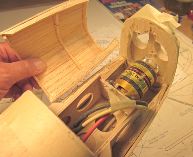
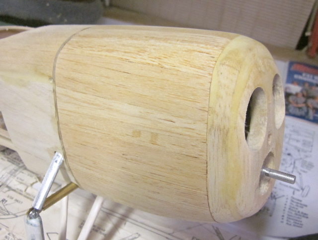
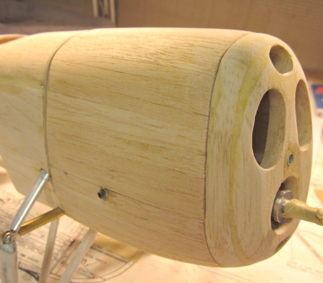
This is the result of all that careful cutting. I left the motor in place during the cowl construction to provide a reliable reference for the prop shaft hole at the front.
Here’s the same just-free cowl from outside. You can use a sanding block to true-up the various mating faces.
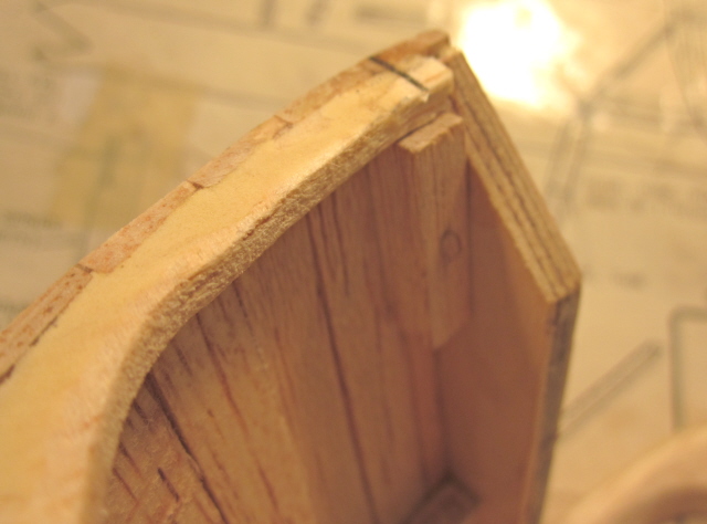
Stay with me…this will make sense soon. This is the right rear corner of the top cowl. I have added a length of 1/4″ square balsa to serve as a reinforcing point for a locating pin.
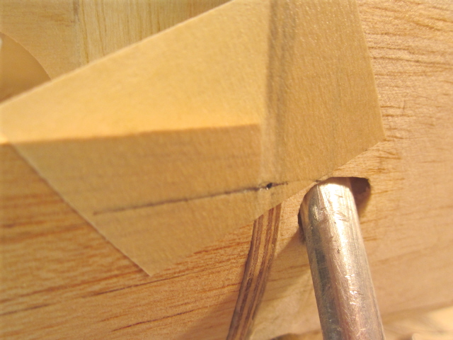
I am marking the location of the center of the 1/4″ sq. block and transferring it to the plywood firewall to which the removeable cowl section will attach.
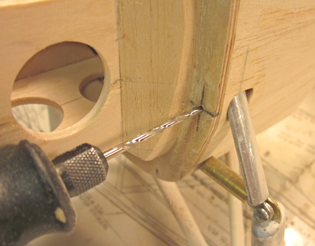
I am going to insert a short piece of 3/32″ I.D aluminum tubing into the firewall as a locating point. This happens on both the left and right sides of the fuselage.
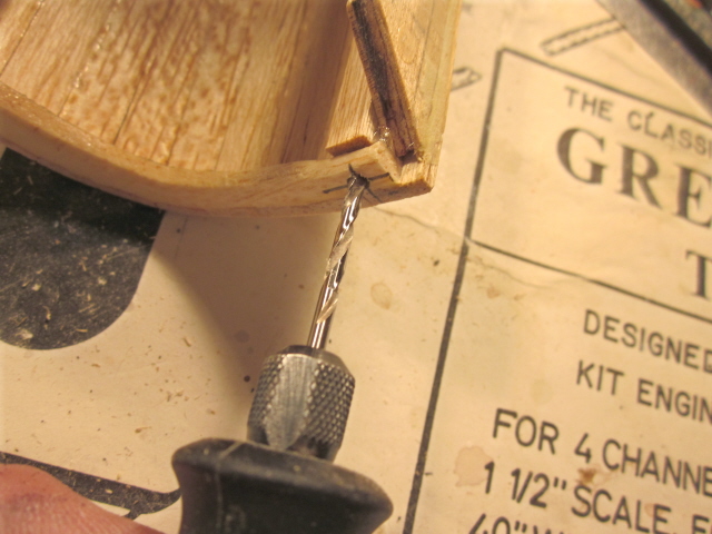
I am drilling a corresponding hole in the rear of the removeable cowl to accept a locating pin that will match the tube in the firewall.
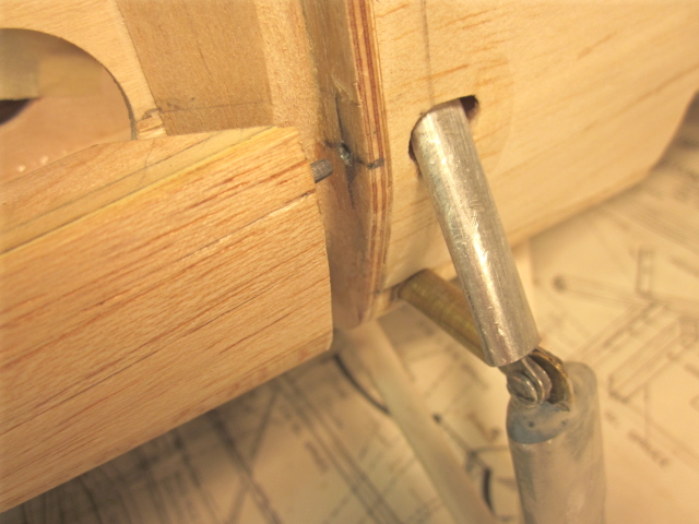
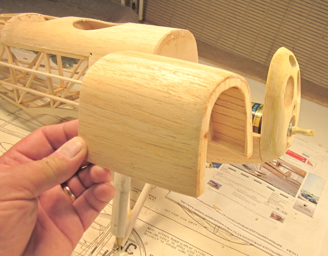
Now you can see how it all works. There is an identical assembly in the right side. When the cowl is pushed back the assembly locks into alignment.
I want the lower cowl to be removeable for maintenance, but will leave it in place during normal operation. The locating pins we just saw are at the bottom corner and the 4-40 machine screws running through the side of the cowl into the motor box, where they are held by blind nuts, lock the entire cowl in place.
This is the entire cowl assembled in place on the firewall, with everything sanded to shape, ready for covering and finishing…but…we are going to have to remove the top cowl section to get at the motor battery and the speed control in the installation I have planned, so the top cowl as you see it is not yet fastened in any way.
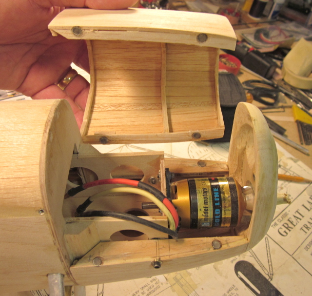
We take care of that by using a bunch of those tiny ceramic magnets. When the top cowl is dropped in place the magnets prevent it from lifting, and the fit between the firewall and nose faces prevents fore-and-aft movement. NOW we’re ready for covering and finishing.
VERY nice Bob!!
Bob,
I’m glad I read this it neatly solves a problem I’m facing updating a 1965 plan set to modern materials and electric Power.
Thanks
Paul